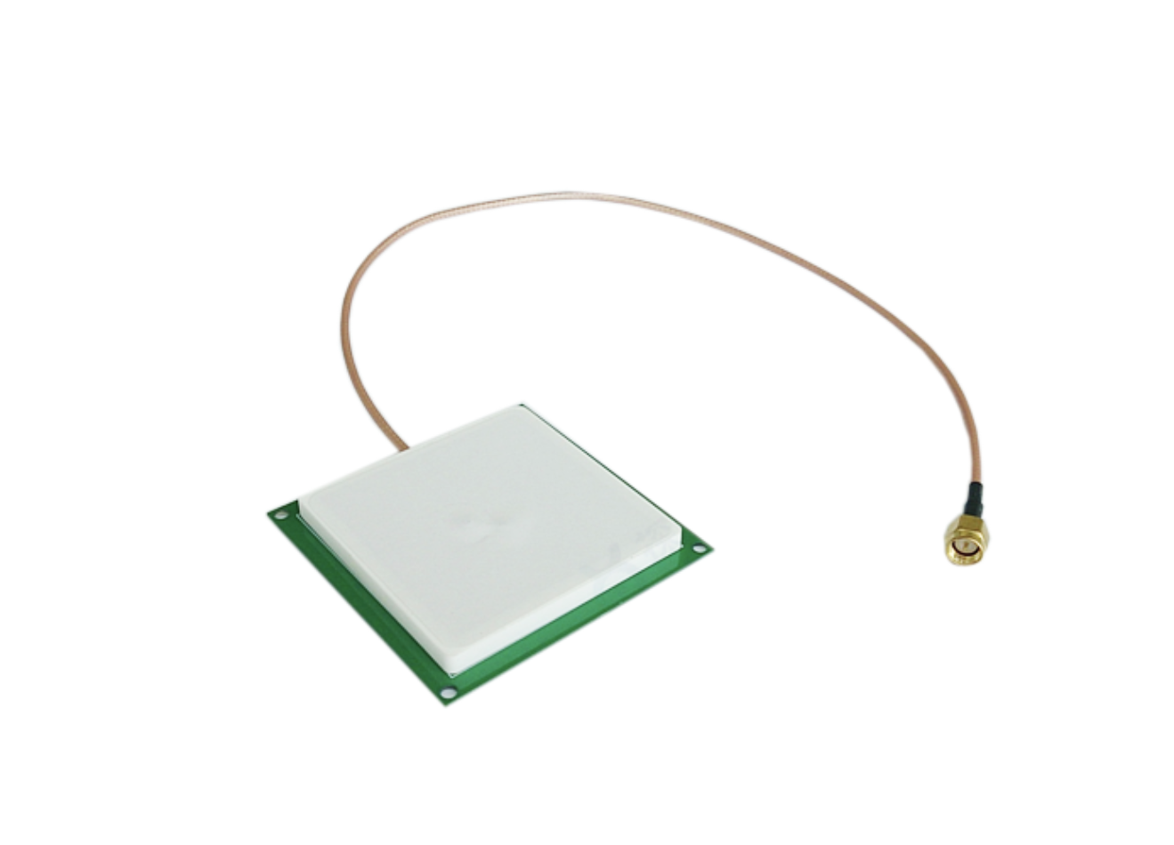
I. Ceramic Antennas
Advantages
•Ultra-Compact Size: High dielectric constant (ε) of ceramic materials enables significant miniaturization while maintaining performance, ideal for space-constrained devices (e.g., Bluetooth earbuds, wearables).
High Integration Capability:
•Monolithic Ceramic Antennas: Single-layer ceramic structure with metal traces printed on the surface, simplifying integration.
•Multilayer Ceramic Antennas: Utilizes Low-Temperature Co-fired Ceramic (LTCC) technology to embed conductors across stacked layers, further reducing size and enabling hidden antenna designs.
•Enhanced Immunity to Interference: Reduced electromagnetic scattering due to high dielectric constant, minimizing external noise impact.
•High-Frequency Suitability: Optimized for high-frequency bands (e.g., 2.4 GHz, 5 GHz), making them ideal for Bluetooth, Wi-Fi, and IoT applications.
Disadvantages
•Narrow Bandwidth: Limited ability to cover multiple frequency bands, restricting versatility.
•High Design Complexity: Requires early-stage integration into motherboard layout, leaving little room for post-design adjustments.
•Higher Cost: Customized ceramic materials and specialized manufacturing processes (e.g., LTCC) increase production costs compared to PCB antennas.
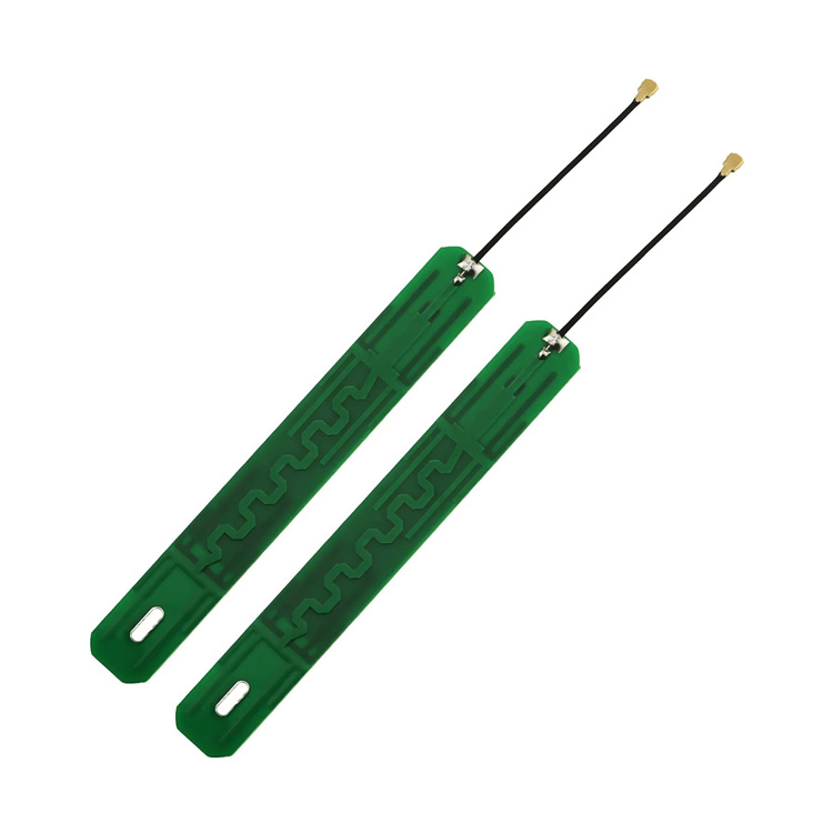
II. PCB Antennas
Advantages
•Low Cost: Integrated directly into the PCB, eliminating additional assembly steps and reducing material/labor expenses.
•Space Efficiency: Co-designed with circuit traces (e.g., FPC antennas, printed inverted-F antennas) to minimize footprint.
•Design Flexibility: Performance can be optimized through trace geometry tuning (length, width, meandering) for specific frequency bands (e.g., 2.4 GHz).
•Mechanical Robustness: No exposed components, reducing risk of physical damage during handling or operation.
Disadvantages
•Lower Efficiency: Higher insertion loss and reduced radiation efficiency due to PCB substrate losses and proximity to noisy components.
•Suboptimal Radiation Patterns: Difficulty in achieving omnidirectional or uniform radiation coverage, potentially limiting signal range.
•Susceptibility to Interference: Vulnerable to electromagnetic interference (EMI) from adjacent circuits (e.g., power lines, high-speed signals).
III. Application Scenario Comparison
|
Feature |
Ceramic Antennas |
PCB Antennas |
| Frequency Band | High-frequency (2.4 GHz/5 GHz) | High-frequency (2.4 GHz/5 GHz) |
| Sub-GHz Compatibility | Not suitable (requires larger size) | Not suitable (same limitation) |
| Typical Use Cases | Miniaturized devices (e.g., wearables, medical sensors) | Cost-sensitive compact designs (e.g., Wi-Fi modules, consumer IoT) |
| Cost | High (material/process-dependent) | Low |
| Design Flexibility | Low (early-stage integration required) | High (post-design tuning possible) |
IV. Key Recommendations
•Prefer Ceramic Antennas when:
Miniaturization, high-frequency performance, and EMI resistance are critical (e.g., compact wearables, high-density IoT nodes).
•Prefer PCB Antennas when:
Cost reduction, rapid prototyping, and moderate performance are priorities (e.g., mass-produced consumer electronics).
•For Sub-GHz Bands (e.g., 433 MHz, 868 MHz):
Both antenna types are impractical due to wavelength-driven size constraints. External antennas (e.g., helical, whip) are recommended.
Concept offers full range of passive microwave components for military , Aerospace, Electronic Countermeasures, Satellite Communication, Trunking Communication applications,antennas : Power divider , directional coupler , filter , duplexer , as well as LOW PIM components up to 50GHz , with good quality and competitive prices.
Welcome to our web: www.concept-mw.com or reach us at sales@concept-mw.com
Post time: Apr-29-2025