Products
-
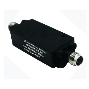
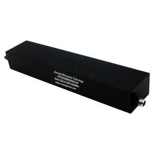
Cavity Notch Filter with 60dB Rejection from 39500MHz-43500MHz
Concept model CNF39500M43500Q08A is a cavity notch filter/band stop filter with 60dB rejection from 39500MHz-43500MHz . It has a Typ. 2.2dB insertion loss and Typ.1.8 VSWR from DC-38000MHz and 45000-50000MHz with excellent temperature performances . This model is outfitted with 2.92mm-female connectors.
-
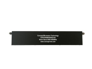
Cavity Notch Filter with 80dB Rejection from 5400MHz-5600MHz
Concept model CNF05400M05600Q16A is a cavity notch filter/band stop filter with 80dB rejection from 5400MHz-5600MHz . It has a Typ. 1.8dB insertion loss and Typ.1.7 VSWR from DC-5300MHz & 5700-18000MHz with excellent temperature performances . This model is outfitted with SMA-female connectors.
-
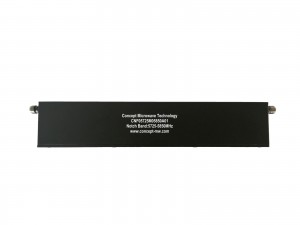
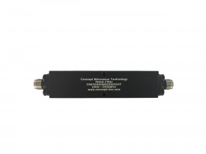
Cavity Notch Filter with 80dB Rejection from 5725MHz-5850MHz
Concept model CNF05725M05850A01 is a cavity notch filter/band stop filter with 80dB rejection from 5725MHz-5850MHz . It has a Typ. 2.8dB insertion loss and Typ.1.7 VSWR from DC-5695MHz and 5880-8000MHz with excellent temperature performances . This model is outfitted with SMA-female connectors.
-
Cavity Notch Filter with 50dB Rejection from 2620MHz-2690MHz
Concept model CNF02620M02690Q10N is a cavity notch filter/band stop filter with 50dB rejection from 2620MHz-2690MHz . It has a Typ. 1.8dB insertion loss and Typ.1.3 VSWR from DC-2595MHz and 2715-6000MHz with excellent temperature performances . This model is outfitted with SMA-female connectors.
-
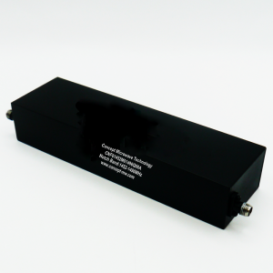
Cavity Notch Filter with 50dB Rejection from 2496MHz-2690MHz
Concept model CNF02496M02690Q10A is a cavity notch filter/band stop filter with 50dB rejection from 2496MHz-2690MHz . It has a Typ. 1.6dB insertion loss and Typ.1.6 VSWR from DC-2471MHz and 2715-3000MHz with excellent temperature performances . This model is outfitted with SMA-female connectors.
-
Cavity Notch Filter with 50dB Rejection from 2400MHz-2500MHz
Concept model CNF02400M02500A04T is a cavity notch filter/band stop filter with 50dB rejection from 2400MHz-2500MHz . It has a Typ. 1.0dB insertion loss and Typ.1.8 VSWR from DC-2170MHz and 3000-18000MHz with excellent temperature performances . This model is outfitted with SMA-female connectors.
-
Cavity Notch Filter with 40dB Rejection from 1452MHz-1496MHz
Concept model CNF01452M01496Q08A is a cavity notch filter/band stop filter with 40dB rejection from 1452MHz-1496MHz . It has a Typ. 1.1dB insertion loss and Typ.1.6 VSWR from DC-1437MHz and 1511-3500MHz with excellent temperature performances . This model is outfitted with SMA-female connectors.
-
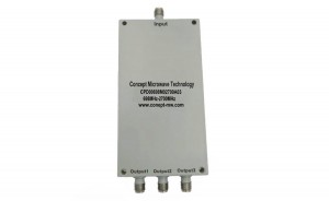
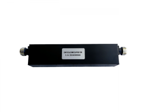
3 Way SMA Wilkinson Power Divider From 698MHz-2700MHz
1. Operating from 0.698GHz to 2.7GHz 3Way Power Divider and Combiner
2. Good Price and Excellent Performances, NO MOQ
3. Applications For Communications Systems,Amplifier Systems,Aviation/Aerospace and Defense
-
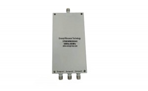
3 Way SMA Wilkinson Power Divider From 500MHz-2000MHz
1. Operating from 0.5GHz to 2GHz 3Way Power Divider and Combiner
2. Good Price and Excellent Performances, NO MOQ
3. Applications For Communications Systems,Amplifier Systems,Aviation/Aerospace and Defense
-
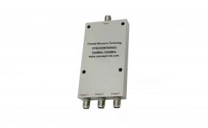
3 Way SMA Wilkinson Power Divider From 500MHz-6000MHz
1. Operating from 0.5GHz to 6GHz 3Way Power Divider and Combiner
2. Good Price and Excellent Performances, NO MOQ
3. Applications For Communications Systems,Amplifier Systems,Aviation/Aerospace and Defense
-
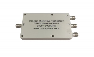
3 Way SMA Wilkinson Power Divider From 2000MHz-8000MHz
1. Operating from 2GHz to 8GHz 3Way Power Divider and Combiner
2. Good Price and Excellent Performances, NO MOQ
3. Applications For Communications Systems,Amplifier Systems,Aviation/Aerospace and Defense
-
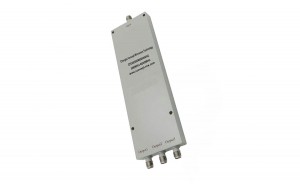
3 Way SMA Wilkinson Power Divider From 2000MHz-18000MHz
1. Operating from 2GHz to 18GHz 3Way Power Divider and Combiner
2. Good Price and Excellent Performances, NO MOQ
3. Applications For Communications Systems,Amplifier Systems,Aviation/Aerospace and Defense